Program Arduino in Assembly or C/C++
This post is a tutorial on how to get started on programming your Arduino in Assembly or C/C++. In order to follow you need a Windows machine and a microcontroller programmer like the Atmel-ICE.
Install Atmel Studio
Download the Visual Studio based IDE Atmel Studio from atmel.com/tools/atmelstudio.aspx. Follow the installation instructions.
New Project
Start Atmel Studio and create a new project (Ctrl+Shift+N). You can choose either C/C++ or Assembler.

On the next screen you will be prompted to select your device. Make sure you select exactly the one you are using. For my Arduino Uno that is “ATmega328P” (“ATmega328” would not work).


Writing the Code
After selecting your device the code editor appears. The following two snippets implement the Arduino Blink Example in both C and Assembly. The output pin is the Arduino pin D13, which is the fifth pin in the PORTB register. The delay between on and off is 1000ms.
Blink in C
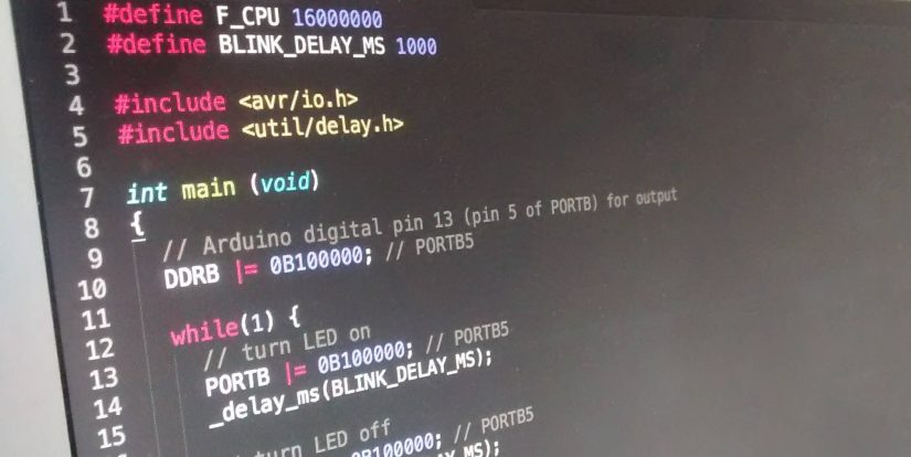
The well-known Arduino Blink sketch implementation in plain C. Note that functions like digitalWrite or delay do not exist. Port manipulation and external header files need to be used instead. The microcontroller’s clock frequency (here $f=16\text{MHz}$) needs to be defined as well.
#define F_CPU 16000000
#define BLINK_DELAY_MS 1000

#include <avr/io.h>
#include <util/delay.h>

int main (void)
{
  // Arduino digital pin 13 (pin 5 of PORTB) for output
  DDRB |= 0B100000; // PORTB5

  while(1) {
    // turn LED on
    PORTB |= 0B100000; // PORTB5
    _delay_ms(BLINK_DELAY_MS);

    // turn LED off
    PORTB &= ~ 0B100000; // PORTB5
    _delay_ms(BLINK_DELAY_MS);
  }
}
Blink in Assembly
Even more complicated: The Blink-sketch in Assembly. While being hard to read without the comments, this very low-level and probably the coolest version.
main:
  sbi 0x04, 5       ; PORTB5 output
loop:               ; main loop begin
  sbi 0x05, 5       ; PORTB5 high
  call delay_1000ms ; delay 1s
  cbi 0x05, 5       ; 5 PORTB5 low
  call delay_1000ms ; delay 1s
  rjmp  loop        ; main loop

delay_1000ms:       ; subroutine for 1s delay
                    ; initialize counters
  ldi r18, 0xFF     ; 255
  ldi r24, 0xD3     ; 211
  ldi r25, 0x30     ; 48
inner_loop:
  subi  r18, 0x01   ; 1
  sbci  r24, 0x00   ; 0
  sbci  r25, 0x00   ; 0
  brne  inner_loop
  ret
While the main program is relatively easy to understand, it’s probably not obvious, how the delay_1000ms function works (thanks to Ido Gendel for investigating on that). On a $16\text{ MHz}$ clock the task of a one-second-delay-function is essentially to keep the CPU busy for 16 million clock cycles.
- The first three
ldi("Loads an 8-bit constant directly to register 16 to 31.") instructions take three cycles in total. subitakes one cycle as well and “subtracts a register and a constant, and places the result in the destination register Rd.” The constant is0x01in the snippet and the execution time is once again one clock cycle.- Each of the following two
sbciinstructions “subtracts a constant from a register and subtracts with the C Flag, and places the result in the destination register Rd”. The constant is0x00in both cases so the only thing that is subtracted is the C Flag. The C Flag however is only set, if the previous subtraction has resulted in an underflow ($0-1\rightarrow255$). - Finally, the
brneinstruction “[…] tests the Zero Flag (Z) and branches relatively to PC if Z is cleared.” This takes two cycles if it branches, otherwise one.
When going through the statements step by step that leads to a total number of $n$ clock cycles for the subroutine body: $$\begin{align}n=&3+256\cdot212\cdot5+256\cdot256\cdot48\cdot5-1\\=&16,000,002.\end{align}$$
Upload and Execute
To actually see an LED blink, you have to connect your Arduino to a power supply and to your programmer. Connect the programmer to your PC.

Make sure the connection plug is facing into the right direction. If not it won’t cause any damage but you will encounter an error during the upload.

Run
Now hit the Run button in Atmel Studio (hotkey F5). The IDE will prompt you to select a programmer (“Please select a connected tool and interface and try again.”).
(1) Select your programmer (e.g. “Atmel-ICE”) and the (2) ISP interface. Also make sure you (3) uncheck “Preserve EEPROM” in the programming settings section. Now you should be able to upload your code (hit F5 again).
The Arduino bootloader needs to be flashed back onto the Arduino, before it can be used in combination with the Arduino IDE again. Starting Electronics has a post that explains how this can be done: Burning the Bootloader to an Arduino Uno using Atmel Studio
Troubleshooting
See Atmel-ICE User Guide and AVRISP MkII Troubleshooting if the following sections do not help.
Failed to set-up tool (no context id returned)
Open the Device Pack Manager (Tools > Device Pack Manager) and install all updates.

Failed to launch program
Error: Failed to start programming session before chip erase with eeprom preserve:Failed to enter programming mode. ispEnterProgMode: Error status received: Got 0xc0, expected 0x00 (Command has failed to execute on the tool)
This could be a connection issue (e.g. the ISP plug is connected the wrong way around). It could also be that your microcontroller is not supplied with power.
Unable to start debug session
“Atmel Studio was unable to start your debug session.
Please verify device selection, interface settings, target power and connections to the target device. Look in the details section for more information.”
Resources
In order to write your own, more complex C/C++ or Assembly programs you are definitely going to need your microcontroller’s data sheet at hand:
Very important for Assembly projects is also the AVR Instruction Set Manual.
Also note that you can view the generated assembly code after compiling a C/C++ project. That can be a good resource for improving assembly skills or for deeply understanding what’s going on behind the scenes. In order to look into the assembly code open the “Solution Explorer”, expand “Output Files”, and open the “.lss” file.

