ShiftRegister PWM Library
The ShiftRegister PWM Library enables usage of shift register pins as pulse-width modulated (PWM) pins. Instead of setting them to either high or low, the library lets the user set them to up to 256 PWM-levels. This post serves as a documentation page for the library and is to be extended over time.
The following video (slides) gives an overview about the library. The source code can be found on GitHub: /Simsso/ShiftRegister-PWM-Library (ZIP-download)
Getting Started
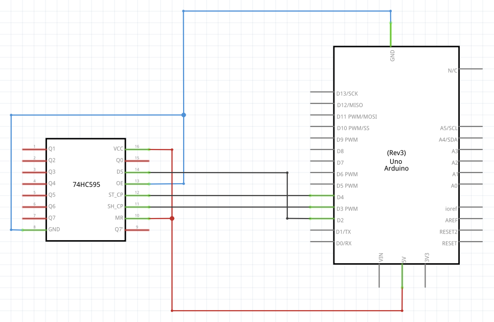
In order to get started, you need an Arduino UNO, a 74HC595 shift register (NXP data sheet), and some LEDs. The figure below shows the wiring (click to enlarge). The LEDs may be connected to the eight shift register output pins (Q0 to Q7). Note that the shift register’s control wires (data, shift clock, and latch clock) are connected to the Arduino pins 2, 3, and 4. These pins can not be changed easily, because the library internally uses port manipulation to maximize performance. The Custom Wiring section of this post explains how these pins can be altered.
After setting up the hardware, download and install the library on your machine. Now you can run the example sketch Sine by uploading the following code. The sketch makes the LEDs of the shift register pulse like a sine wave (as shown in the introduction video).
#include "ShiftRegisterPWM.h"

ShiftRegisterPWM sr(1, 16);

void setup()
{
  pinMode(2, OUTPUT); // sr data pin
  pinMode(3, OUTPUT); // sr clock pin
  pinMode(4, OUTPUT); // sr latch pin

  // use timer1 for frequent update
  sr.interrupt(ShiftRegisterPWM::UpdateFrequency::SuperFast);
}

void loop()
{
  for (uint8_t i = 0; i < 8; i++) {
    uint8_t val = (uint8_t)(((float)
      sin(millis() / 150.0 + i / 8.0 * 2.0 * PI) + 1) * 128);
    sr.set(i, val);
  }
}
The key things to note from the sketch above are:
- Create a shift register object. An explanation for the
resolutionparameter can be found in the next section. It is important to keep the resolution as low as possible because the memory consumption grows linearly with it.ShiftRegisterPWM sr(numShiftRegisters, resolution); - Enable timer interrupts, i.e. automatically update the shift register output pins using timer 1 of the ATmega328P. The parameter defines the clock frequency (see next section for a table of possible values).
sr.interrupt(ShiftRegisterPWM::UpdateFrequency::SuperFast); - Set the i-th pin of the shift register to a PWM value between 0 (always off) and 255 (always on). If the output resolution is set to a lower value, e.g. 8, the PWM value will be scaled down accordingly.
sr.set(i, val);
Terminology
Pulse-width modulation (PWM) is a technique for encoding information in a digital signal through pulsing. See Wikipedia for details. The Arduino Uno has six pins that support PWM output (namely 3, 5, 6, 9, 10, and 11) which can be accessed using the function analogWrite. In some cases, however, more PWM pins might be required. This library makes the pins of a shift register PWM capable.
A shift register in our use-case is a storage that can be serially fed with digital values. In case of the 74HC595 shift register, it outputs the last eight bits of data in parallel.
The PWM carrier frequency, denoted as $f_\text{carrier}$, is the frequency that at which PWM pulses are emitted. Its inverse value is the period. The Arduino’s carrier frequency is $490$ or $980$ Hz by default (reference).
The PWM clock frequency, denoted as $f_\text{clock}$, is the maximum frequency at which outputs can be changed. Some possible values are predefined and listed in the table below. They can be passed to the interrupt function. For example like that:sr.interrupt(ShiftRegisterPWM::UpdateFrequency::SuperFast);
| Name | Clock frequency $f_\text{clock}$ |
|---|---|
| VerySlow | $\approx6,400\text{ Hz}$ |
| Slow | $\approx12,800\text{ Hz}$ |
| Medium | $\approx25,600\text{ Hz}$ |
| Fast | $\approx35,714\text{ Hz}$ |
| SuperFast | $\approx51,281\text{ Hz}$ |
The PWM resolution $r$ is defined to be the fraction $r=\frac{f_\text{clock}}{f_\text{carrier}}$. Intuitively, it can be understood as the number of different brightness levels that LEDs can take when connected to the shift register. The resolution can be manually set on initialization of a shift register object (it is the second parameter of the constructor). Possible values are $r\in(0,255]$. For the Arduino’s PWM pins it is fixed to $r_\text{Arduino}=256$.
Stacking Shift Registers
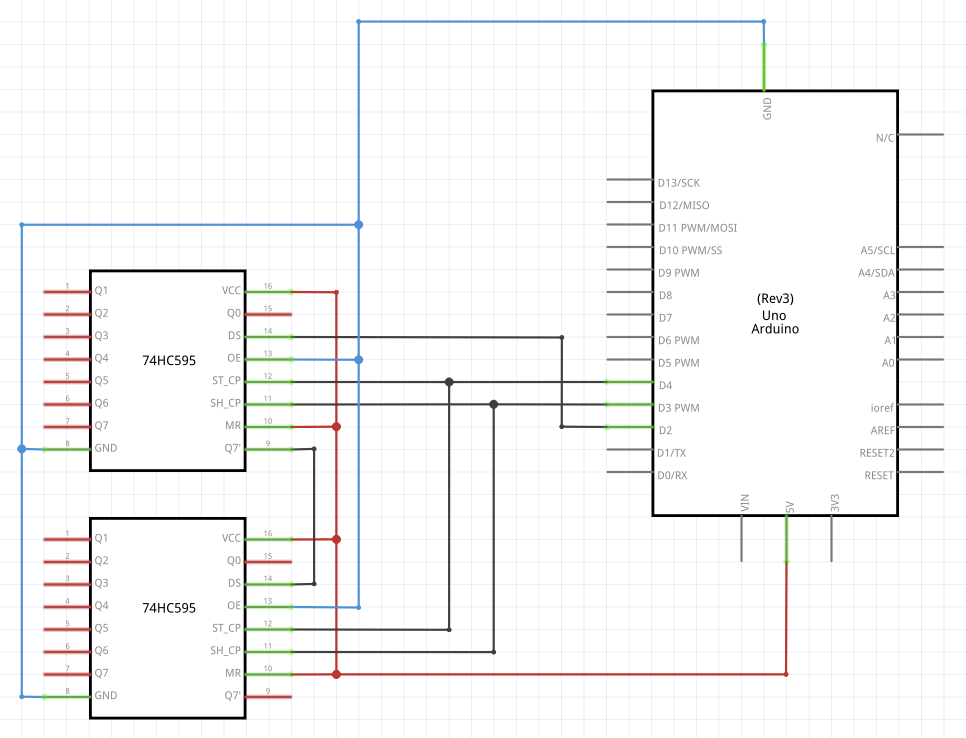
The library support serial operation of multiple shift registers. The 74HC595 can be chained as shown in the following circuit diagram (click to enlarge).
Now, the ShiftRegisterPWM constructor needs to be called with the corresponding number of shift registers. For the circuit diagram above that would be srCount=2.
ShiftRegisterPWM shiftRegisterPWM(srCount, resolution);
The time it takes to update the shift register output pins increases with the number of stacked shift registers. Therefore it is strongly recommended to decrease resolution $r$ and $f_\text{clock}$ with an increasing number of shift registers.
Custom Wiring
By default, the shift register must be connected to the Arduino UNO’s digital pins 2, 3, and 4.
| Arduino | Shift register | Role |
|---|---|---|
| D2 | DS | Serial data |
| D3 | SH_CP | Serial data transmission clock |
| D4 | ST_CP | Shift register output flip-flop clock |
While other libraries for different purposes offer to manually set the pins by passing them as parameters, the ShiftRegister PWM Library does not offer that for performance reasons. Nevertheless, there is an option to change the pins. For each of the three wires, two macros can be defined which contain (1) the port and (2) a bit selection mask. The following table lists the macros with descriptions and the default value.
| Name | Default | Role |
|---|---|---|
| ShiftRegisterPWM_DATA_PORT | PORTD | Register name of the bit that corresponds to the data pin |
| ShiftRegisterPWM_DATA_MASK | 0B00000100 | Byte that masks the bit that corresponds to the data pin (2) |
| ShiftRegisterPWM_CLOCK_PORT | PORTD | Register name of the bit that corresponds to the serial clock pin |
| ShiftRegisterPWM_CLOCK_MASK | 0B00001000 | Byte that masks the bit that corresponds to the serial clock pin (3) |
| ShiftRegisterPWM_LATCH_PORT | PORTD | Register name of the bit that corresponds to the latch clock pin |
| ShiftRegisterPWM_LATCH_MASK | 0B00010000 | Byte that masks the bit that corresponds to the latch clock pin (4) |
The macros can be overwritten by making a definition prior to including the library. In the following snippet, the latch clock pin is set to be the digital pin 8 (instead of 4).
#define ShiftRegisterPWM_LATCH_PORT PORTB
#define ShiftRegisterPWM_LATCH_MASK 1
#include "ShiftRegisterPWM.h"
The associated example sketch is called CustomPins. Details regarding the register names and bit masks can be found in the Arduino port manipulation guide.
Custom Timer
In order to update the digital pins of the shift register with the desired PWM frequency, the library uses timer interrupts. The library registers an interrupt if the function sr.interrupt() is called. Note that this works only for a single shift register object (or multiple in serial). If (1) multiple PWM shift registers shall be used in parallel, (2) an exact frequency is required, or if (3) the timer is not available for usage, e.g. because another library is already using it, it is possible to manually configure the library to use another timer. For calculating the compare-match-register values, I recommend using a timer interrupt calculator tool. The example sketch CustomTimerInterrupt demonstrates manual timer operation mode.
The library registers the timer 1 interrupt service routine (ISR) depending on a macro. In the source code, this is implemented as follows:
#ifndef ShiftRegisterPWM_CUSTOM_INTERRUPT
  // Timer 1 interrupt service routine (ISR)
  ISR(TIMER1_COMPA_vect) { // function which will be called when an interrupt occurs at timer 1
    cli(); // disable interrupts (in case update method takes too long)
    ShiftRegisterPWM::singleton->update();
    sei(); // re-enable
};
#endif
Therefore, with writing #define ShiftRegisterPWM_CUSTOM_INTERRUPT prior to the library import, the redefinition of 'void __vector_11()' error can be prevented and timer 1 is spare.

